 7.7. Rendering
  7.7. Rendering
 Once a radiosity solution has been computed, the next step is to render an image. To render an image, each object in the scene is projected onto an image plane. Then, with view parameters and view direction supply, visible surfaces at each pixel on the screen are determined. A modified depth buffer algorithm is used to evaluate the visibility of all elements in the environment. However, instead of storing intensity information, the modified algorithm stored visible element identfication numbers for each pixel in a buffer. That buffer is called element buffer [Cohen,86]. The final pixel intensity value is then calculated by bilinearly interpolating the radiosities at the corners of the element.
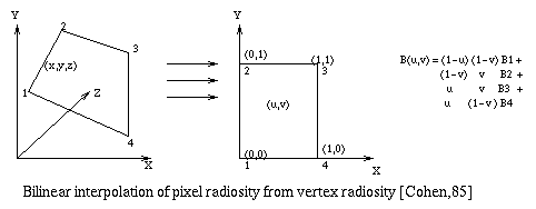
After intensity values at each element corners are obtained, the bilinear interpolation method is used to determine the radiosity of each pixel for the renderer. The bilinear interpolation ensures first order continuity at patch edges.
In order to perform bilinear interpolation, the intersection point between a ray shot from the eye through a pixel and the element is determined. This procedure gives the corresponding world coordinates of the intersection point. This x,y,z position is then converted to parametric (u,v) coordinates within the element. This value is used to interpolate an intensity value for that point.
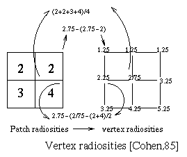
Radiosity values of patches are transferred to each vertex
of the patches. For each polygon, the vertex intensities of
patches which are interior to that polygon are computed by
averaging the radiosities of the surrounding patches. For the
vertex intensity values which are exterior to the polygon, these
are evaluted by extrapolating values from the adjacent interior
vertex radiosities through an average of the adjacent patches
radiosities. Finally, the resulting vertex radiosity values are
used for the bilinear interpolation within each patch [Cohen,85].
As interpolation is performed in object space, the interpolated
values remain unchanged when the view position is moved.

Fig. 7.46 : Vertex Radiosities

Fig. 7.47 : Bilinear Interpolation
Gouraud shading has been used to render the objects for most algorithms in which objects are polygonalised. Basically, Gouraud shading requires vertex intensities of the polygon. The main advantage of using this shading method is its speed and simplicity. This method is preferable for real-time interactive applications such as walk-throughs and simulation of dynamic scenes. As Gouraud shading is used only to render the objects and not perform any energy transport calculation, it gives the effecitve speed. [Kwok,92]
To reduce the computational time, some algorithm perform the linear interpolation directly in image plane during the rendering processs. The most common method for Gouraud shading is an incremental formulation of linear interpolation designed for hardware scan conversion. During the hardware rendering, intensity values defined at polygon vertices are linearly interpolated along the polygon edges as it's scaned. At each scanline, these values are then interpolated horizontally between the two closest edges which intersecting the scanline [Cohen,93].
However, Gouraud shading has limitations mainly because it requires polygonal meshes. Some limitations are specifed by Cohen [Cohen,93].


