 7.6. Radiosity Solutions
  7.6. Radiosity Solutions
 As we have seen, the form factor between every pair of
patches in the scene is calculated. Since there are n patches in
the environment, there will be a set of n linear equations and
they may be solved by direct or iterative matrix method. The n
equations will be written in matrix form as below:
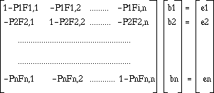
The computational time and the large amount of memory required are major issues in radiosity. To overcome this problem, Cohen introduced a new approach - Progessive refinement method - which significantly reduces the memory requirement and improves the processing time. General idea is - an initial quickly rendered image is presented to the user. This image is then progressively refined in a continuous and graceful way without distracting the viewer. This process will correctly simulate the global illumination of the diffuse environments, hence, it gives the higher quality and greater realism. As it provides the view independent solution, refinement process may continue without interrupting the user as the user views the scene from different directions.
In previous methods to calculate the radiosity of a given
environment, the matrix described above was solved simultaneously
by using Gauss-Siedel method. However, in progresssive refinement
approach, the matrix was solved one row at a time. Therefore, ith
row of the equation gives an estimate radiosity value of patch i
based on the current estimates radiosity values of other patches
in the scene. This result is then contributed to the radiosities
of all other patches - in Cohen's term, Shooting light out from
that patch into the environment. Cohen also uses the term
Gathering to present the lights arriving at a particual patch
from all other patches in the scene at one iteration. Note that
the hemicube algorithm is still used to determine form factor
Fij, by placing the hemicube at each patch i.
In mathematical form, as we have seen, the radiosity of patch i is its emitted energy plus contribution from other patches in the scene.
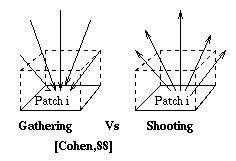
Fig. 7.38 : Gathering versus Shooting
The unique feature about PR method is each intermediate solution is displayed as the iterative solution progresses. Intermediate results then simultaneously improve the solution of other patches in the scene. Maximum visual difference between each stage is obtained by choosing the patch with the current maximum unshot energy. Next patch to be chosen will be the one that received the most light from the light source and so on. By doing so, the final radiosity value, Bj, of a given patch j will approach the final value in the earlier stage in the process as the largest contributions are added first. Reordering of the patches also provides an accurate solution in less than a single iteration, hence, reduces the computation costs. For a dynamic environment, absolute unshot energy of least recently moved patch or the most recently shadowed pached may be used providing that the viewer is stationary.
Since each intermediate result is presented to the user as the solution progresses, displayed image will progress from a dark environment to a fully illuminated scene. In the early stages of the solution, there will be no accurate interreflections between objects, thus, regions do not receive direct illumination - this will be inadequate. Therefore, for the earlier stages, the global illumination is approximated by adding an arbitary ambient term. The ambient value is based on the current estimate of the radiosities of all patches and reflectivity of the environment at any given stage. Note that this value is not added to the actual solution. It is only used for the display purpose. As the solution progresses , the ambient term will be decreased gracefully.
Thus, radiosity of Bi which used in display will be

Bi = Bi + Pi Ambient


    do

      Select surface with greatest reflected and/or

        emitted energy

      Computed form factors from that surface to all

        surface element in environment

      Based on form factors, add contribution from source

        surface to radiosity of each element

    until converged

      [Baum,89]

Two pass image synthesis is a combination of ray tracing method and radiosity method. It accurately evalutes the specular component and the diffuse component of the illumination. The first pass, called preprocess, is a view independent algorithm which is based on the traditional hemicube method with an extension to achieve the diffuse transmission, and specular to diffuse reflection and transmission. The second pass, called postprocess, is a view dependent solution which is based on the distributed ray tracing algorithm in which takes the result of first pass and evalutes the specular component.
As we have seen, for an environment containing specular and diffuse surfaces, there are four mechanisms to be accounted for
This new method accounts for all four mechanisms of light transfer. Preprocess, or view independent solution, determines the diffuse component of intensity of all surfaces with additional specular transport. Specular transport is accounted for only to the extent necessary to accurately calculate the diffuse component. The result from preprocess is then taken as the source during the postprocess. Postprocess accounts for the specular to specular and diffuse to specular light transfers. Each pixel in the final image is then produced by adding the specular component to the diffuse component.
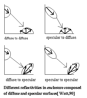
Fig. 7.39 : Radiation Exchange
In the preprocess, or view independent algorithm, the diffuse component of intensities of all the surfaces in the scene are evaluted. In addition, it also determines the diffuse transmission and specular transmission which effects the diffuse component.
To include the transmission, a normal imaginary hemicube is contructed at the front of the interested patch as well as at the back of the patch. The front hemicube determines the Fij value while the back hemicube evalutes the backwards from factor, Tij, to represent the lights seen by the back of the translucent surface.
The next extension is to account for the specular
transmission, particularly in the event of two diffuse surfaces
which see each other through a specular transmitting surface. As
shown in the diagram below, the incoming energy of patch i is the
contributions from all other patches that see patch i plus
contribution of patches P which are seen through from translucent
surface patch j. The latter contribution can be determined by
summing the integrals of light intensity over patches P which are
visible through patch j. This form factor is called window form
factor, denoted by Tf,ijp. This is determined by normal hemicube
algorithm, by projecting the patches P and patch j onto the
hemicube of patch i and taking the overlap pixels as a result.
The result is the areas of patches P which seen by patch i
through patch j.
Preprocess also accounts for specular to diffuse light transfer. As shown in the diagram below, diffuse patches B and A will see each other directly as well as via specular patch, C. In this event, specular surface, C, is treated as an additional route and an extra form factor is added to represent the additional fraction of energy transfer over that route. This additional form factor is a form factor between a patch and a virtual patch in a virtual environment. It is called a mirror form factor. Mirror form factors can be easily calculated in the same way as normal form factors once the geometry of the virtual world is determined.
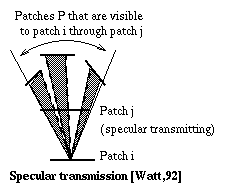
Fig. 7.40 : Specular Transmission
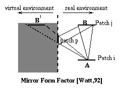
Fig. 7.41 : Mirror Form Factor
The postprocess takes the result of preprocess and
evaluates the specular to specular and diffuse to specular light
transport using ray tracing approach. An incoming intensity at
the point of interest is all the light coming to that point over
the hemisphere. However, Wallace makes the assumption that only a
fraction of the incoming intensities over the hemisphere will
make a significant contribution to the outgoing intensity of that
patch. To achieve that, a rectangular reflection frustum is
constructed at that view. That frustum is a square pyramid whose
front face is divided into nxn pixels.
The incoming intensity that is seen by the pixels of reflection frustum are the ones seen by that pixel. Visibility is determined by using a standard Z-buffer algorithm with a low resolution of the order of 10x10 pixels. However, this incoming intensity may contain both a diffuse and specular component. The diffuse component is determined during the preprocess using the Gouraud shading by evaluting the vertex intensities of the patches.
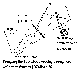
Fig. 7.42 : Postprocessing
If a surface visibility in the reflection frustum pixel is specular then the entire process is applied recursively as in normal ray tracing. The work required for this recursion can be reduced by adaptively limiting the depth of the recursion and by reducing the resolution of reflectin frustum for suceesive bounce.
This method presents a way to construct a hierarchical representation of the form factor matrix by subdividing the patches into sub-patches or elements according to a user supplied error bound. In the previous method, form factors are evaluted to a higher precision than is necessary. The resulting image may also contain the artifacts where form factors have large error. This technique uses the combination of multi-resolution and careful analysis to overcome the above problems. This algorithm also guarantees that all form factors will be evaluted to a same precision. For the visibility determination, ray tracing algorithm is used. This method also takes advantage of visibility coherence between different levels of detail and the observation that most interactions between patches are either fully visible or full invisible with respect to each other.
The hierarchical subdivision algorithm provided in this method is inspired by methods solving the N-body problem. In N- body problem, there are n particles and each of them exerts a force on all n-1 particles, which imply that there are n(n-1)/2 pairwise interactions. All the forces on one particle can be calculated in less than quadratic time by using two key ideas -
Appel [Appel,85] stated that the N-body is solved hierarchically by approximating the forces between particles in two clusters with a single force, when the seperation between the cluster significantly exceeded their sizes. This is solved by O(n) time.
Hanrahan found that there are many similarities between the N-body problem and the radiosity problem. The similarites are :
However, there are a few differences between those two methods. They are :
Hierarchical radiosity algorithm recursively decomposes a polygon into a hierarchy of patches and elements, then it constructs a hierarchical representation of the form factor matrix. This matrix stores the interactions of patches at different levels of detail.
Initially, the form factor between two patches, Fij and Fji, is estimated by using normal form factor computation. If the estimated form factor values are less than a user-supplied error bound than it is assumed that the true form factor value is approximated. Interaction between the two patches is then recorded. On the other hand, if the form factor value is more than the specified value, the patch with large form factor is subdivided into four new quadrilaterals by splitting it at its center. In this data structure, not only the leaf nodes but also the intermediate nodes have the list of information on patch interactions. The subdivision is terminated if the patch area is smaller than the predetermined area. If there is no further subdivision available, then two patches are forced to interact. This process is then applied recursively to each patch in the environment.
As the process makes sure that form factor values are less than the predetermined value, form factors corresponding to each iteration will have approximately the same magnitude. The process would terminate if the error associated with the form factor integral between the two interacting patches exceeds the given upper bound.
The form factor calculation which is described above is only accurate if a patch is completely visible with respect to the other patch. However, since occlusion plays an important role in a realistic environment, the algorithm is modified to take into account the visibility consideration. Even though occulsion is difficult to detect, the intervening surfaces reduce the light transport between two patches, and therefore, the form factor in the presence of occulsion is never greater than the form factor estimated above. Form factor with the effect of occlusion can be determined by multiplying the estimated form factor with visibility correction factor. Visibility correction factor estimates the percentage that each patch sees of the other. This value is only needed when the refinement process is terminated.
Therefore, the form factor with visibility determination
will be :

      F  = Ve Fe

      Fe is the estimated form factor without considering occlusion

      Ve is the estimated visibility


     T(n) = F(n) V(n)

     F(n) is number of form factors computed

     V(n) is the cost of performing the visibility test for

          a set of n elements.

The recursive refinement process can be reduced by visibility determination. If two sub-patches are totally invisible relative to each other, then patch subdivision process can be immediately terminated. If two patches become fully visible, there is no need for further visibility tests between them. Lastly, if two patches are partially visible to each other, futher refinement would need additional visibility computation. However, as the patches are recursively subdivided and their visibility will full into two catergories - either totally visible or totally invisible, only those on the fringes will be remained partial.
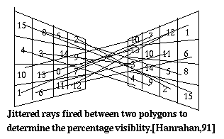
Fig. 7.43 : Jittering
This algorithm is an extension to the hierarchical radiosity method. This method is introduced by Smits [Smits,92]. It uses an adaptive subdivision scheme with two closely related light transport processes : one propagating energy from the light sources and the other propagating Importance from the visible surfaces. This algorithm is inspired by important functions which have been used in neutron transport theory.
As we have seen in Substructuring method, the areas where high intensity gradient values are subdivided into smaller areas in order to get an accurate radiosity solution. As a result, there are vast number of interactions to be handled, consequently it increases the computational cost. This problem is approached by Hanrahan [Hanrahan,91] by focusing the effort on the significant energy transfers and approximating the insignificant interactions. The method considered all potential interactions among the surfaces but each interaction is computed to the appropriate level of accuracy. The Importance-driven radiosity method extended the above technique by refining the interactions contributing the most error to the view-dependent solution [Smits,92].
Two basic categories of illumination method in computer graphics are : radiosity method and ray-tracing method. Radiosity methods simulate the propagation of light throughout an environment. In the sense of neutron transport theory, it is simulating the process of photons emanating from the light sources. On the other hand, ray-tracing simulates only the light reaching the eye. In neutron transport term, it traces rays that emanate from the eye but it behaves very much like photons in every other respect [Smits,92].
The apprach to photon transport used in neutron theory is very similar to those used in radiative transfer to predict neutron flux. If the flux arriving at one surface is required, it is typically the adjoint of the original transport equation which is solved, in effect reversing the direction of neutron migration back toward the source. This strategy can be related to various ray tracing methods such as backward ray tracing [Smits,92]. Nuclear engineers have found that taking advantage of interdependence between two tranports, the solution can be accurately approximated. By combining those two transport equations, the overall solution gives higher accuracy than either component alone.
Applying this observation in global illumination, instead of using these dual processes in multiple passes to simulate light scattering, we use two processes together - solving them simultaneously. Thus, in order to produce an accurate result more quickly, this algorithm uses radiosity and imporatnace together for the visible scene. This is done by refining estimates of the transport equation most where the interaction of radiosity and importance is highest.
Generally, radiosity and importance are similar in many
respects but they are not totally the same. Radiosity is flux
density whereas importance of a patch is the fraction of emitted
radiosity that reaches the eyes, hence, it is dimensionless
[Smits,92]. For simplicity, mathematical equations are omitted
here(you can refer to [Smits,92] for details.)
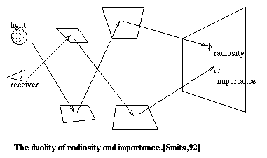
Fig. 7.44 : Radiosity and Importance
Consider an iteration between patch i and j - which
involved radiosity propagation and importance propagation. If an
error occured which is high, one of the two patches involved is
subdividived using hierarchical algorithm. New interactions for
the refined system is then computed.
The above diagrams illustrated the two patches i and j with high importance and high radiosity, repectively. The links shown in left diagram carries the radiosity from i to j in the direction of arrow and importance from j to i, against the arrow. As the effect of interaction on error is not too high, evaluation takes place at high level of hierachy (notice only one link). However, the diagram on the right shows the propagation of radiosity from j to i and importance from i to j. This transfer has greater potential effect on error, hence, the process carries onto lower level of hierachy (notice more links) [Smits,92]. Therefore, the general idea is if the interaction exceeds the specified tolerance value, the interaction is refined by subdividing the patch with greater area.
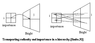
Fig. 7.45 : Radiosity and Importance and Hierarchy
Since importance or radiosity value of a patch is related to its parent or its children, the values have to be redistributed up and down in a hierachical system. The radiosity value is not changed when it is pushed down from a parent to its children whereas importance has to be recomputed according to the propotional area of each child. In that way, every patch receives the appropiate contribution from its ancesters and descendants.


