 7.4. Modelling the scene
  7.4. Modelling the scene
 To compute the radiosity value of a given environment, first of all the scene must be modelled. Since the scene model is used in the radiosity computation, the model has to meet several requirements in order to get an accurate solution. Modelling algorithms are generally independent of the radiosity solution technique used for scene modelling.
Before we model a given environment, first of all we have make sure that the model is built in a consistent manner. That is, not only the scene is represented in a geometrically consistent manner but that it also contains sufficient information to satisfy the radiosity algorithm requirements. The basic model geometry constraints are as follows :-
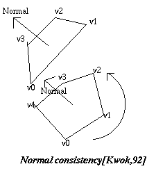
Fig. 7.16 : Normals
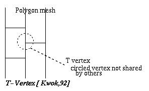
Fig. 7.17 : T Vertices
When calculating the radiosity values, a given environment is broken down into a fixed number of small areas called patches (details explained in next section). To be able to get an accurate solution, meshes or patches have to meet certain requirements. The requirements are-
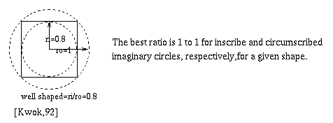
Fig. 7.18 : Aspect ratio of inscribed circle
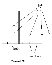
Fig. 7.19 : Light leaks
In traditional radiosity, the environment is broken down into small areas called patches and each patch is assumed to have uniform radiosity value [Goral,84][Cohen,85]. This method gives a poor result when the patches are large relative to the area over which high gradients occur. Therefore, surfaces with high gradients such as shadow boundaries and penumbras should be subdivided into finer grids or patches [Cohen,86].
Cohen first introduced the substructuring method in 1986 to
produce an accurate image of a given environment. In this
approach, the objects are hierarchically subdivided into
surfaces, patches and elements. Surfaces are composed of polygons
and curved surfaces. Patches are obtained by subdividing the
surfaces. Patches are convex polygons which consists of one or
more elements and their intensity may vary over the patch area.
Elements are planar polygons with a smallest geometric unit in
which intensity is assumed to be constant( See the diagram
below).
The advantages of this method over traditional patch dividing method are :

Fig. 7.20 : Structure Hierarchy
Unfortunately, there are some drawbacks in this method. Such as :
Baum[91] presented an automatic mesh generation method which works with various modelling constraints. In order to create an initial patch mesh, fixed lengths of rectangular grids are superimposed on top of each surface by aligning them with edges of a surface (note that other grids such as an equilateral triangular grids may be used as well). Since the grids length are fixed for all the faces, output polygons are well shaped with no T-vertices.
The length of the grids is determined by uniformly subdividing the longest face edge. However, poorly shaped patches can occur when the edge length of the input face is small compared to the length of the grid edges. This problem can be solved by using a different radiator density (grid length) for different surfaces. Surfaces that have short edges can have small grid edge lengths, while those without short edges can have longer grid edge lengths.
Patches with high density variation will then be subdivided into smaller patches by using a bilinear subdivision method. The patches and elements of a surface are stored in a tri-quad tree, in which patches are at the top level and each points to a tri- quad tree whose root is an element identical to the patch. The resultant element mesh also has to meet certain constraints as described above(mesh requirements). Mesh elements are generated by four-to-one midpoint subdivision. Using that type of subdivision, if the parent patch is well shaped, the children elements also will be well shaped.
To maintain gradual mesh density changes, there should be
at most one subdivision level difference between two neighbouring
elements in the same face (see the diagram below).
However, problems arise when an element is subdivided without subdividing its neighbours. T-vertices can be created at the common boundaries. To eliminate these T-vertices, the neighbour elements of newly subdivided element are split by connecting corners of neighbouring polygons to the T-vertices. Hence, splitting is localized to prevent excessive meshing (see diagram below, notice there are no T-vertices).
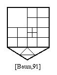
Fig. 7.21 : Mesh density
There are two different splitting arrangments for triangular and four for rectangular patches.
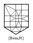
Fig. 7.22 : Mesh subdivision
Like all other methods, Baum automatic mesh generation method has some drawbacks.

Fig. 7.23 : Splitting of the Mesh


