 7.3. Thermal Engineering concepts behind radiosity
  7.3. Thermal Engineering concepts behind radiosity
 Radiosity originated from the Radiation Heat Transfer principle within the field of Thermal Engineering. Thus, we need to know the heat transfer concepts to be able to understand radiosity properly.
Radiation is electromagnetic energy in transport, in wave form with vibration transverse to the direction of propagation. It orginated from an energy input such as light bulbs or excitation of particles. If the excitation comes from the molecular bombardment which characterises temperature then the radiation is called Thermal Radiation[Siegel,72]. In radiosity, we are only interested in thermal (or light) radiation exchange between surfaces.
To explain the radiation exchange between surfaces -
imagine a hollow enclosure with temperature E1 and containing
surface A with temperature E2. Temperature E1 is greater than
temperature E2.
From the first law of Thermodynamics (exchange of energy from a hotter to a cooler body) there will be radiation exchange between surface A and the walls of the enclosure. A while later, the enclosure will reach a common uniform equilibrium temperature, called the equilibrium state.
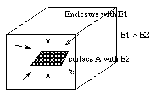
Fig. 7.2 : Radiation exchange between surfaces
Now move surface A to another position or rotate it to another orientation. Surface A must still be at the same temperature since the whole enclosure remains isothermal. Consequently surface A must be emitting the same amount of radiation as before. To be in equilibrium, the surface must still be receiving the same amount of radiation from the enclosure walls [Siegel,72][Hottel,67].
Therefore, we can conclude that radiation exchange between surfaces of a body hold the following rules
When radiation is incident on the surfaces, some of the radiation is reflected and the rest penetrates into the body. For the emissivity and reflectivity of diffuse surfaces, the following restrictions hold:
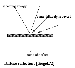
Fig. 7.3 : Reflection from diffuse surface
Consider an enclosure made up of N discrete diffuse surfaces. Each of the surfaces in the enclosure will have emitted and reflected energy. With regard to the reflected energy, two assumptions are made:
Also, the reflected energy for each surface has the same diffuse and uniformly distributed character as the emitted energy. Hence, the reflected and emitted energy can be combined into a single energy quantity leaving the surface [Siegel,72].
In the radiation exchange, all surfaces of the enclosure are assumed to be ideal diffuse reflectors, ideal diffuse light emitter, or a combination of both. If diffuse light sources are used, such sources are treated as surfaces of enclosure with specified illuminating intensities. If directional light source such as spot lights are used , the surfaces directly illuminated by the source are identified and treated as diffuse light sources. Hence, all reflected and illuminating light in the enclosure are ensured to be diffuse [Goral,84].
For each surface in the enclosure, there will be an incoming energy and outgoing energy. The light arriving at surface j is denoted by Hj (incomming intensity) which is the sum of intensity contributions from the other N-1 surfaces. The light emerging from the surface j is denoted by Bj (outgoing energy).
For outgoing energy Bj, we need to consider two parts :
In diagram below, an imaginary surface is sketched above the actual surface, shown by dashed line. To an observer, the intensity Bj (radiosity) is coming out from the imaginary surface.
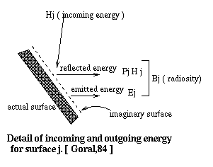
Fig. 7.4 : Energy Transfer
We can write Bj in mathematical terms like this :-

Fig. 7.5 : equation 1
However, Hj is the sum of flux from all surfaces in the
enclosure that see surface j. The fraction of flux leaving the
surface i and arriving at surface j is specified by term form
factor, Fij. Since there are N surfaces contribute to the
irradiation onto surface j, we can write Hj like this:

Fig. 7.6 : equation 2
We have to include surface j because it might see itself,
if the surface is concave.
So combination of equation 1 and 2 is:
and this equation applies to all the surfaces in the enclosure [Goral,84].

Fig. 7.7 : equation 3
Since there exists N surfaces in the given environment, there will be N equations and those equations are solved simultaneously. The solution is called the Radiosity method solution. This method will be explained in detail under the section on "Radiosity solution"
In this section, the radiation exchange in an enclosure composed of specularly and diffusely reflecting surfaces will be considered. When a combination of such surfaces are involved, we need a mechanism to cater for the following types of reflections :-
As a mathematical term, the total rate at which radiant energy leaves the surface is (as explained in above section) :
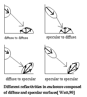
Fig. 7.8 : Radiation Exchange
Since it does not depend on the type of reflection occuring, it will apply for both diffuse and specular surfaces.

Fig. 7.9 : equation 1
However, there is a difference in interpretation of the
reflectivity of a surface, Pj. For diffuse reflectors both
emitted and reflected intensities are uniform over all
directions: thus the same directional character and the diffuse
configuration factor can be applied to both terms. However, for
specular reflection, the reflectivity term, PjHj, will have a
directional distribution different from the diffuse emission, Ej.
Thus, when the surface j is specular, the outgoing energy, PjHj ,
should be spilt into a specular term and a diffuse term, Psj and
Pdj respectively [Siegel,72].
Therefore, Pj will becomes
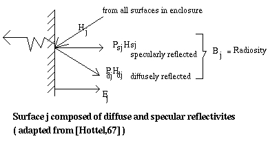
Fig. 7.10 : Energy components
However, the incident radiant energy arriving at surface j, will have two components: some are from diffuse surfaces and some are from specular surfaces.

Fig. 7.11 : equation 4
To expand equation 5 :

Fig. 7.12 : equation 5
Nd = number of diffuse surfaces out of N total surfaces

Fig. 7.13 : equation 6
The form factor Fij is given as :
Therefore, radiosity of surface Bj in enclosure composed of specularly and diffusely reflecting surfaces will be (by substituition of equation 1 with 2 and 6 :
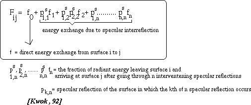
Fig. 7.14 : equation 7
Fij can be expanded in the above equation. But for clarity, it is left for the reader to figure out.

Fig. 7.15 : equation 8


