 3.4. Analogue devices.
  3.4. Analogue devices.
 The device sends an analogue or continuously variable
signal to the computer which is changed by an Analogue to Digital
converter into a digital value that the machine can use.
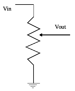
Symbol is Variable Resistor, third connection can be changed to tap off different voltages like volume control. This Vout is used to indicate different coordinates, rates of change, etc.

Fig. 3.6 : Variable resistor
Variable resistor is used in most analogue devices.
Dials: Simple variable resistor or potentiometer used to give
digital information

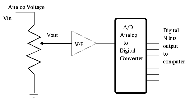
Fig. 3.7 : Dial

Vout changes as the tap is moved.

The Voltage Follower is used to isolate the potentiometer

from the A to D. This and any other components between pot

and the A/D must not change the voltage in any way

(must not change as temperature changes, as supply voltage changes).

 The A/D is an analogue to digital converter and takes

analogue signal (voltage 0 to Vin) and converts to N binary bits.

Note T4010 uses this approach with two potentiometers to control X and Y coordinate of cross hair. A joystick will also use this mechanism.


