 3.3. Cross-hairs.
  3.3. Cross-hairs.
 Typically interactive devices are used in conjunction with a graphics cursor which tracks the physical cursor such as on a digitiser or "tracks" due to a deflection - trackball, joystick, etc.
This tracking and positioning can then be used to pick an
object or to position the cursor for the next graphics action -
draw, delete, shade, etc.

A menu can be set up to perform some action and this can be

chosen using the pick device.

 Position cursor or cross hair in appropriate box

to give command: Use knowledge of convex bodies

if box is other than rectangular.

Many graphics terminals support cross-hair input facilities: the user sends a command to graphics device to enter cross-hair mode, manipulates the cross-hairs until the required (x,y) point is reached and then hits a key to indicate that some action is to take place at that point. The device then sends the character hit plus the (x,y) coordinate back to the users program.
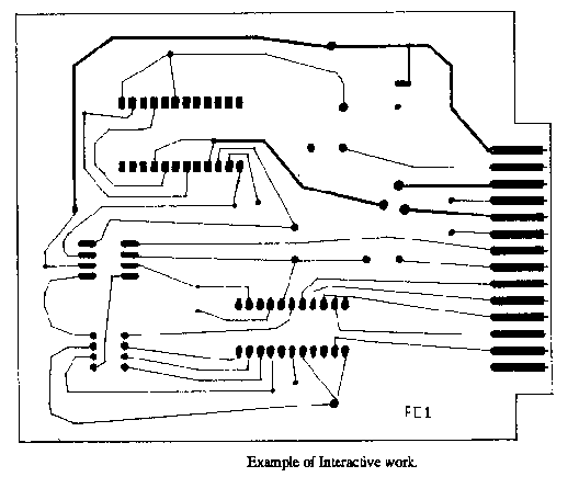
In Figure 3.1 the Printed Circuit Board was created
interactively using the crosshair facility of the graphics
terminals. The key pressed indicated the type of object to draw
(tape,finger,pad) and what angle, size, etc it was to be drawn
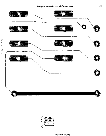
with. Further examples of these basic components are shown in
Figure 3.2 and 3.3.

Fig. 3.1 : Example of Interactive work.

Fig. 3.2 : Example of Interactive Scaling (31K bytes).


